I recently built a new home server, it’s a multipurpose box that will hold most of my infrastructure and also is a file server with a lot of hard drives (and room for more in the future) All of these drives meant this ended up being a very large machine so there was space to put them all. I ended up getting a CaseLabs Magnum THW10 for the case, which has space for a ton of stuff in it. While the machine is working great and doing everything I need it to, there is one small problem with it. The front fans aren’t spinning fast enough.

The hard drives are mounted behind the front intake fans and I want to make sure they keep cool. All the output from the PWM fan headers on the motherboard, an ASUS Z10PE-D16, are tied to the CPU temperatures. But, the CPUs doesn’t really get too hot in the server so the case fans rarely (if ever) go above their minimum speed. My normal solution for this problem is to use the fancontrol utiltity which is part of lm_sensors. However, lm_sensors is not able to detect any of the fan controllers on the motherboard. I think this is because the fan control is done by the BMC on the motherboard and lm_sensors doesn’t support the BMC. I wasn’t able to find an option for fan control in the BMC’s web interface, so I’m not sure. Either way I decided it would be much easier to just build a fan controller to be able to manually set a fan speed for the input fans.
Building a Fan Controller
The server has 8 front 120mm fans, 1 rear 120mm fan, and 6 top exhaust 140mm fans installed. However, because the motherboard only has a few fan headers I have 2 Silverstone CPF04 powered splitters. The front 8 fans are connected to one splitter and the 6 top exhaust fans to the other. For this project I wanted to just stick a controller in between the motherboard 4 pin fan header that enable me to adjust the PWM control signal sent to the fans. This would only take power from the motherboard and generate it’s own independent PWM output. Since the splitters are independently powered I wouldn’t need to worry about routing power from the motherboard to the fans.
There are commercial solutions out there, like the Noctua NA FC1, which are pretty close to what I was looking for. The problem with the Noctua controller for my use case was that it wouldn’t let me set full manual mode if the motherboard header was plugged in. I could create a custom cable that didn’t have the PWM pin connected, but then I would be paying for a bunch of features that I didn’t actually want.
Designing the controller
I did some searching on google to see what most people were doing because building a fan controller is hardly a unique thing. Most examples that I found built a circuit with a 555 timer in astable mode with a potentiometer to adjust the duty cycle of the output waveform. So I decided to do the same thing. After reading the Intel specification for 4 wire PWM fans I figured out my design constraints for the oscillator. The circuit needed to have an output frequency of ~25 kHz and operate at 5 volts. Given this I settled on this circuit:
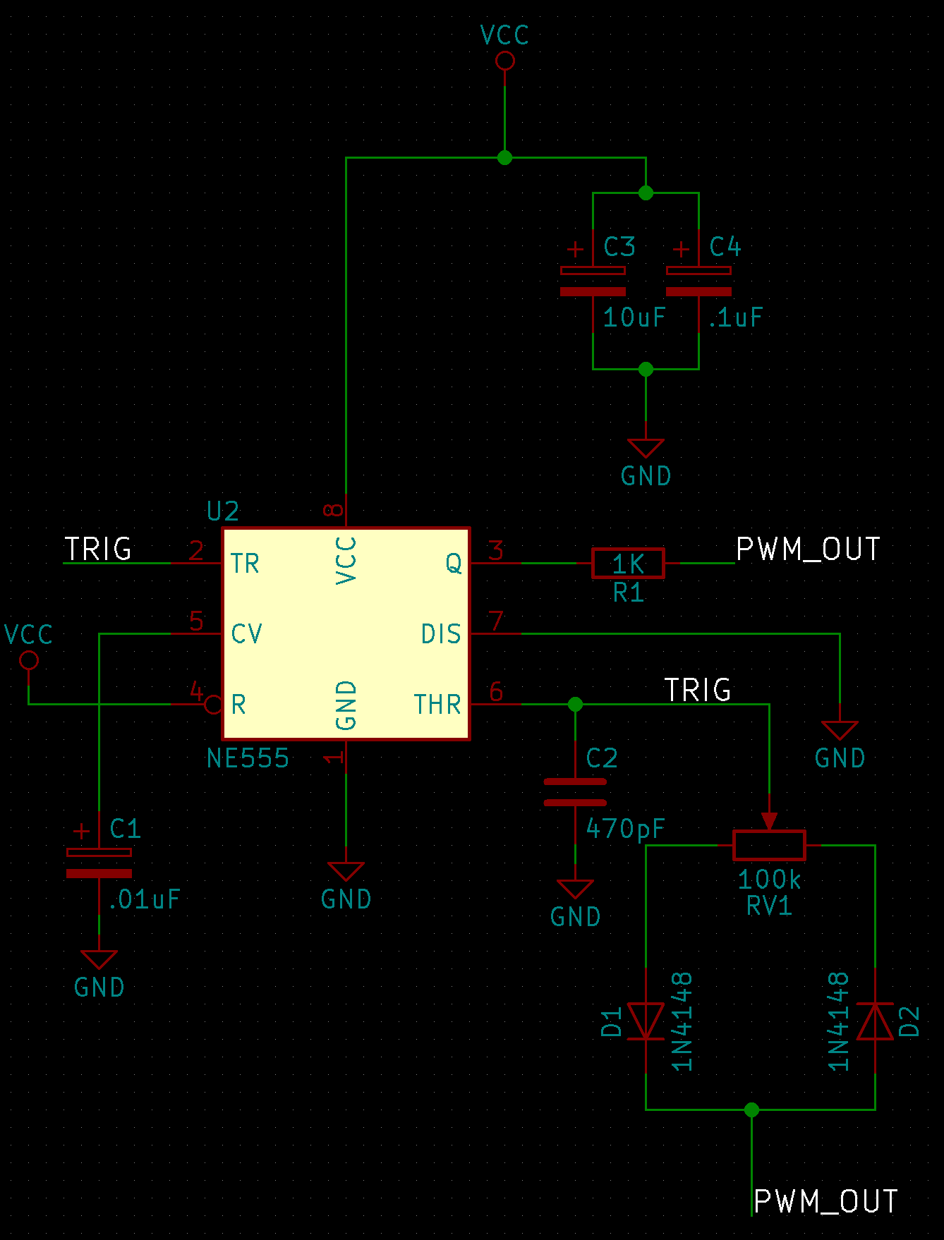
It was mostly borrowed from the circuits I found via searching the internet for similar projects. But I had to adjust some of the component values to meet fan control spec.
From there I designed a PCB for this circuit using KiCad. I specifically designed the PCB to be easy to assemble, using all through hole components. While I could have easily made it much smaller using surface mount components I wanted this to be a good project for people just starting soldering. This isn’t a very complex project and I felt like there might be people out there with a similar need for it. But, even with this constraint the board is still fairly small at only 35mm x 44mm. (mostly because it’s a simple circuit.
All the designs for this are open source and can be found on my github at:
https://github.com/mtreinish/pwmcontroller
Putting together the Controller
After finishing a functional design I sent it out to elecrow to get the board manufactured. A couple weeks later I got the boards delivered. (I cheaped out on the shipping which made it take longer, the boards were manufactured in < 1 week)
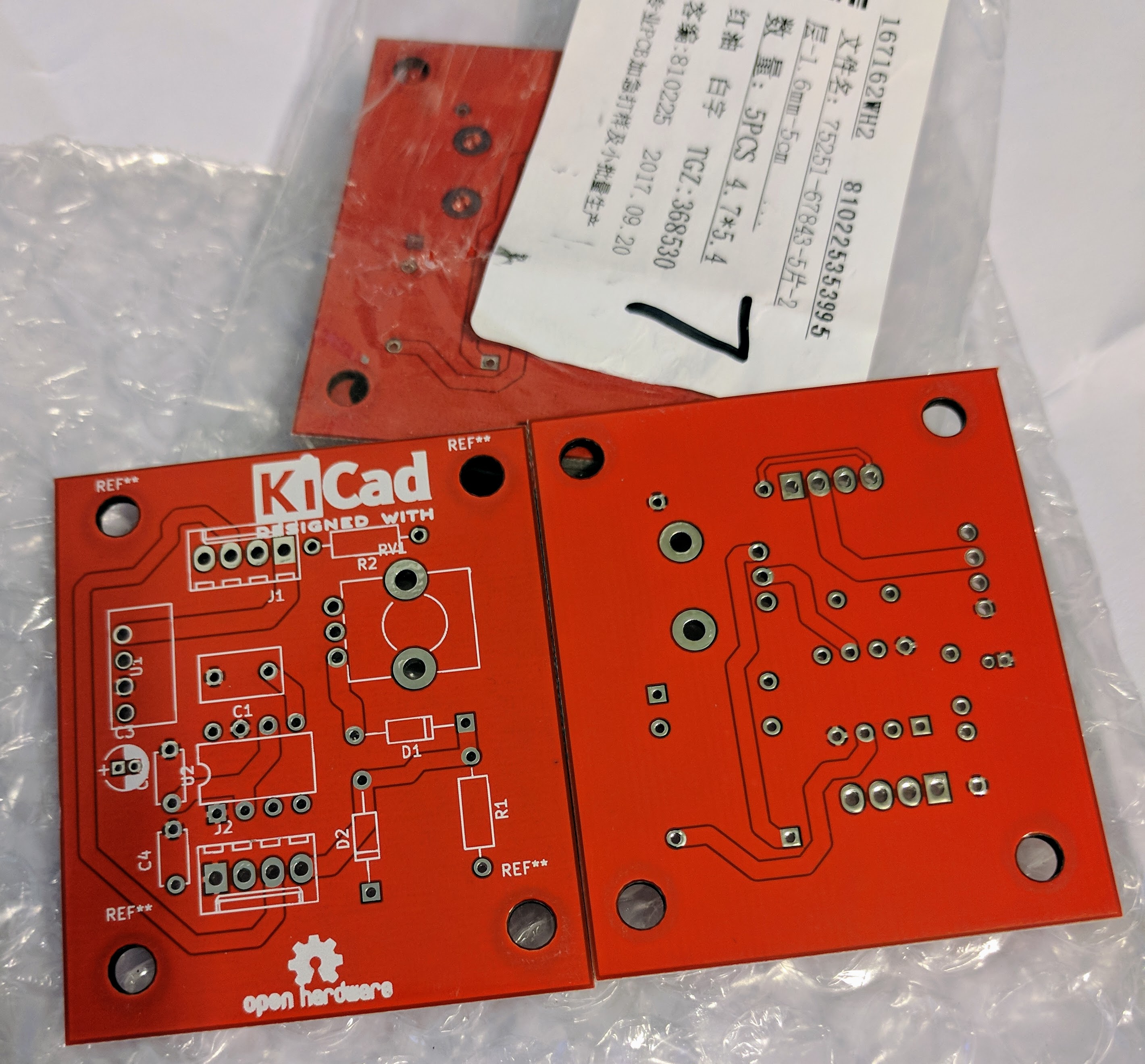
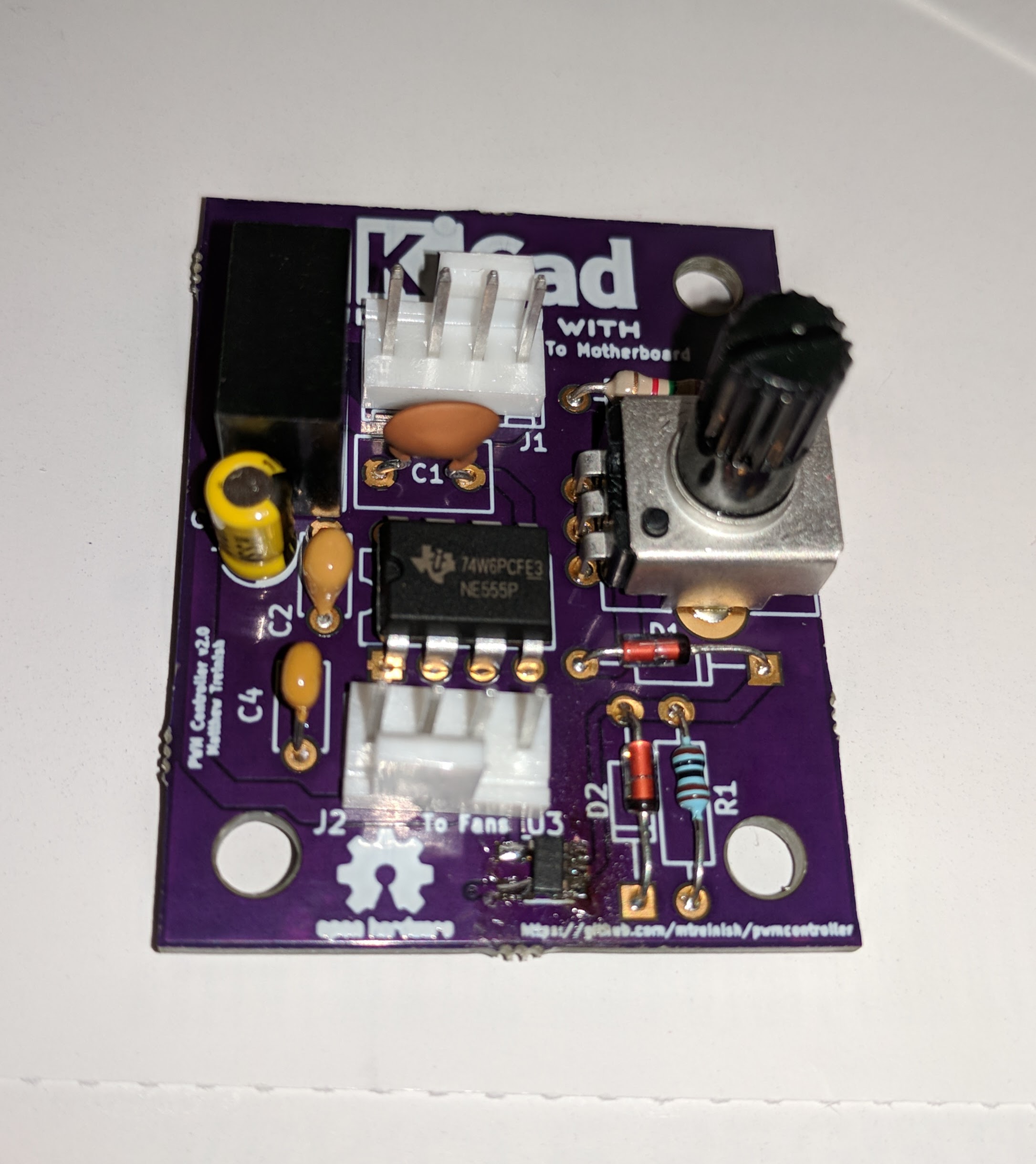
Then I soldered the components onto the board

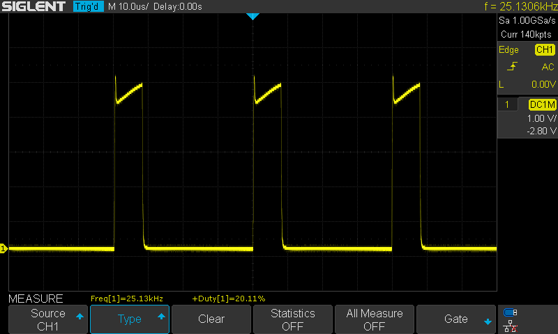
Then I installed the new controller in my server, and of course it didn’t work. So I took the PCB to my bench and tested it with an oscilloscope, a bench power supply and a spare fan. It turns out there were two issues. First, the 555 timer was outputting at 3.8-4.2V instead of the 5V called for in the spec. The second issue was that the output wasn’t really a square wave either:
Second Attempt
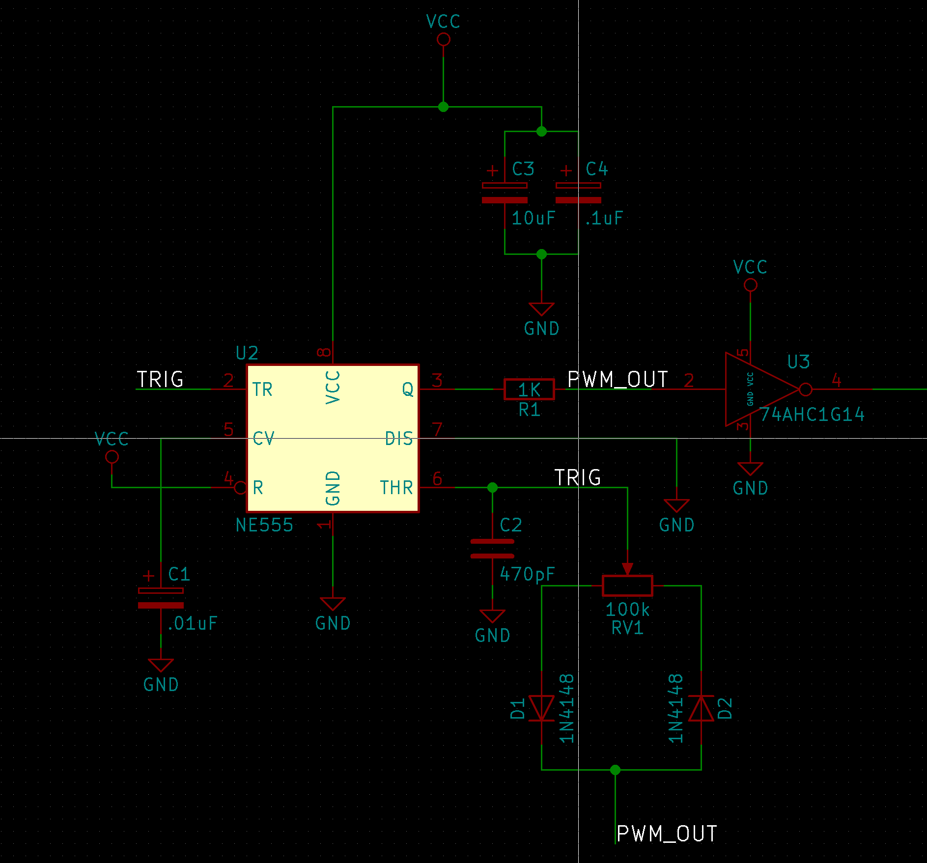
To correct the issues I found from the first attempt, I modified my circuit slightly and added a schmitt trigger on the output. This would have three advantages: it would clean up the square wave, make the rising and falling edges much faster, and it would ensure we have a stable 5V output. It’s actually pretty funny, I decided/remembered to use the schmitt trigger because I had to write a fake app note for a class in college on using a schmitt trigger for switch de-bouncing.
The modification to the circuit schematic was pretty simple. Just add the schmitt trigger to the output of the 555 and then wire that to the fan header:
The only complication to this came on the board layout. I was not able to find a single Schmitt trigger in a through hole package. The only through hole schmitt triggers that I found (granted I didn’t do an exhaustive search) was a 4 or 6 way in a DIP-14 package. Which would be by far the largest package on the board. I wanted the PCB to be simple, small, and easy to hand solder. This originally meant all through hole, but with the choice between a DIP 14 and increasing the board size or a single surface mount component I opted to go with the SMT components. I was able to find one from TI in a SOT-23-5 package, which honestly isn’t hard to solder, it just takes a little patience. (magnification helps)
After finishing up the revised board layout (I shrunk it down a lot and cleaned things up at the same time) I sent it out to OSH Park to get manufactured:

Then I soldered everything on:
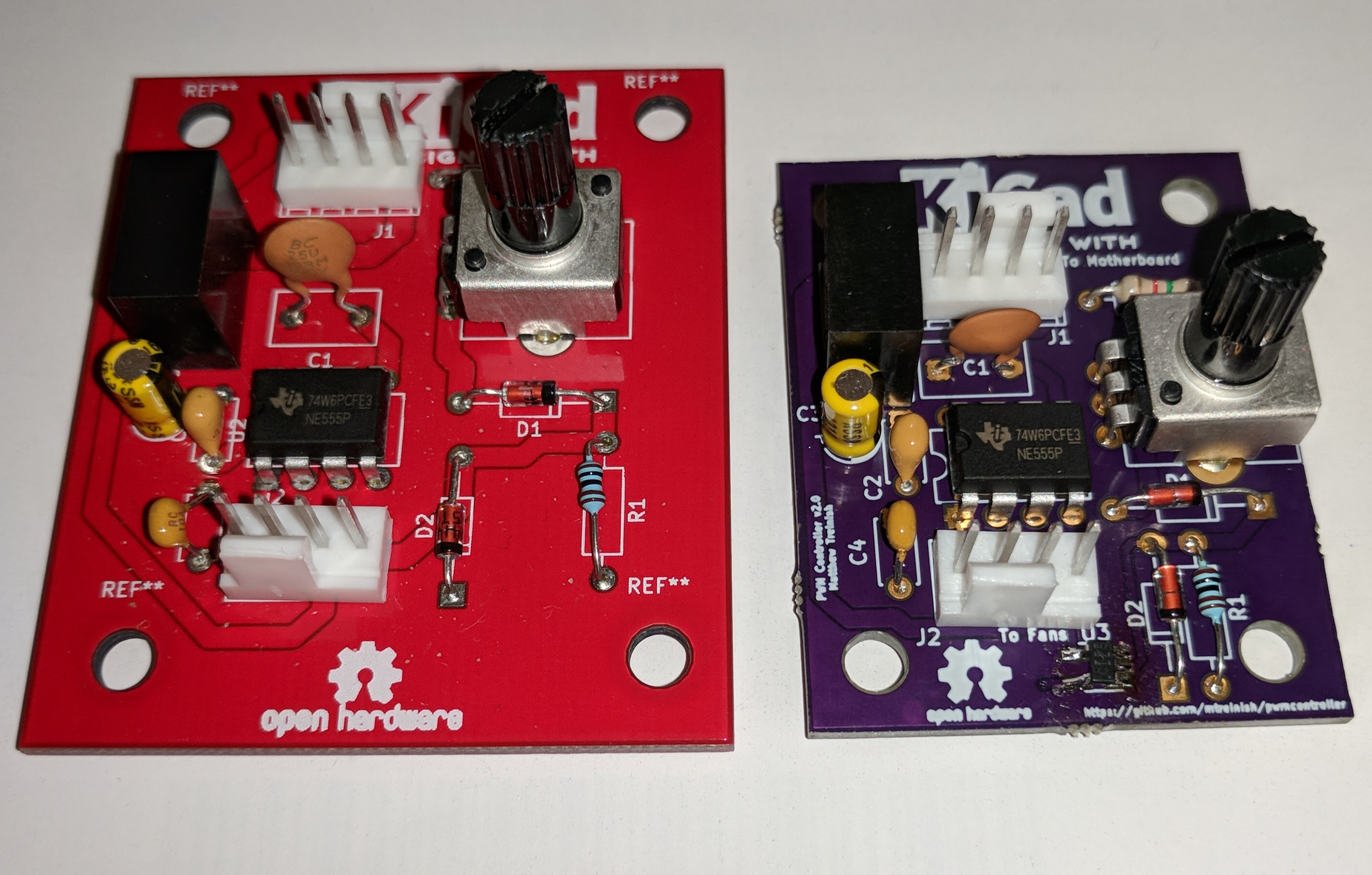
I did make one mistake on the new board; I forgot to connect the ground from the motherboard connector and the 5V side of the DC/DC converter. Nothing a small bodge wire between pins 1 and 3 on the DC/DC converter couldn’t fix. (the pcb design in the git repo has been updated with this correction already) With that and the new schmitt trigger things worked perfectly:
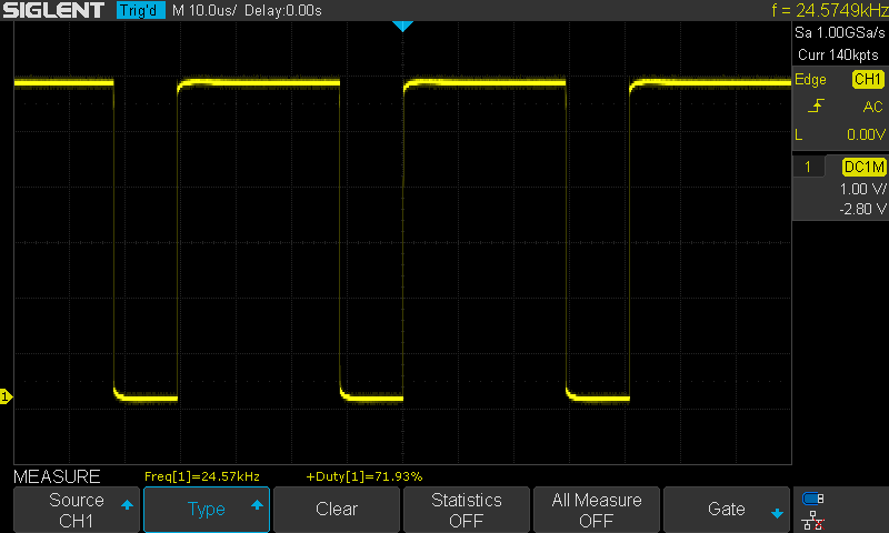
and putting it in my server now I can control the fan speeds very easily.
Conclusion
This project made me realize that a lot of the random controllers and accessories on modern computer motherboards that we take for granted and are completely closed designs. There isn’t any documentation from ASUS about how things on my server motherboard are wired up or the protocols they utilize (at least not that I was able to find). I started thinking about my other computers including my desktop and how I’m controlling things like the fans and water pump there. It’s the same story there; I’m relying on the motherboard’s (an ASUS Rampage V Edition 10) baked in hardware and software. I checked and lm_sensors isn’t able to talk to the fan controller on the desktop either. But, unlike my server the desktop’s UEFI provides me the necessary level of control to adjust the temperature input and set custom fan curves.
While I would like to see these designs opened up to make it easier to leverage, I realize that’s not very likely to change any time soon. But in the mean time I we can continue to just build open alternatives for the pieces we need. I’m currently working on another fan controller project for my desktop to try and start addressing this. I’m going to build a multi-fan controller similar to something like an aquacomputer aquero. But, built in an all open manner and with an open and defined interface. You can follow the in progress of that effort here: https://github.com/mtreinish/openpwm It’s still super early in the hardware design and it’s going to be a very long term project I work on in my free time.
This is really interesting. I was part of a group of people who were playing around with 555-based PWM fan controllers a few years ago, and the brains of the group devised a relatively simple three stage circuit with a 555 outputting to a LM311 comparator and into a second 555 for a super clean and accurate square wave.
I built the circuit years ago and still use it regularly to control fans for testing purposes. The frequency is easy to change – I have it configured for 16KHz which works well with pretty much every intel-spec PWM fan, and swapping out one cap means I can change it to 5Khz on the fly.
I’m no electronics engineer but I’d love to put the circuit on PCB at some point.
This is a really interesting project – thanks for sharing!